Overview
This article describes the steps used to configure multiple VLANs for both OPNsense and a physical switch connected to the LAN-side of the OPNsense firewall. The purpose of introducing VLANs to my homelab environment is to separate the LAN network into dedicated logical networks, providing improved security and reducing broadcast traffic for each of the networks. Prior to this project, all devices were members of the default LAN.
What is a VLAN?
Virtual Local Area Networks (VLANs) allow the splitting of a physical network into multiple logical networks. This helps to group devices and workloads logically, allowing for dedicated networks per device group or environment, with each VLAN acting as a security boundary. VLANs are quite commonly used with home and commercial wireless networks to provide separate main and guest WiFi networks.
Benefits
- Easier to assign policies, DHCP ranges, firewall rules, etc.
- Isolate untrusted devices such as lab VMs, or guest devices.
- Reduce the blast radius if a device or subnet becomes compromised.
- Implement fine-grained firewall rules between VLANs using OPNsense.
- Reduces hardware requirements, no need to extra switches or NICs.
- Less ARP/broadcast noise on each subnet.
- Better performance and lower latency.
How do VLANs work?
VLANs work by adding a 4-byte label to Ethernet frame headers so that VLAN capable switches and devices can recognize which logical network (VLAN) the frames belong to. The Ethernet frames can be tagged or untagged.
Tagged:
- Ethernet frame contains a VLAN ID in its header. Used between VLAN-aware devices (switches, wireless APs, routers).
- If the Ethernet frame is tagged, the VLAN ID tells the switch which VLAN it belongs to.
- Labeled traffic for VLAN-aware links.
Untagged:
- Ethernet frame has no VLAN ID. Typically used by end-user devices, computers, phones consoles that are not VLAN-aware.
- If the Ethernet frame is untagged, the switch uses the PVID (Port VLAN ID) to decide which VLAN to assign the frame to.
- When an untagged frame arrives, the switch tags it with the port’s PVID so it can be forwarded within that VLAN.
- When a frame leaves an access port, the switch removed the VLAN tag before sending it to the device.
PVID:
- The default VLAN ID (native VLAN) the switch uses to assign to untagged Ethernet frames.
- PVID only matters if something sends untagged traffic to the port.
- Every switch port has a PVID set to assign a native VLAN to untagged traffic.
Access Port:
- Carries a single VLAN, frames sent and received are untagged.
- Switch assigns all incoming untagged traffic to the VLAN defined by the PVID setting.
Trunk Port:
- Carries multiple VLANs, frames received are tagged.
- All VLANs on a trunk are sent as tagged frames.
- Can define a single VLAN for untagged using the PVID method.
Design
This design will create a separation of the management portion of the network from the default LAN (native VLAN 1). This management VLAN will contain Proxmox nodes and other future devices related to virtualization or storage.
Virtual servers (VMs) will reside on separate dedicated VLANs 20 and 99, ensuring they remain separate from the management VLAN. In some cases, firewall rules will be added to allow specific traffic to flow between the VLANs for purposes such as monitoring, backup or other tasks that require traffic to enter another VLAN.
This design will utilize IPv4 only.
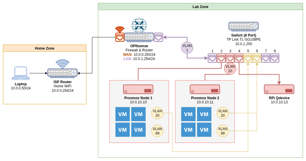
Design Layout:
|
|
Networks:
| VLAN | Name | Subnet | Purpose |
|---|---|---|---|
| – | WAN | 10.0.0.250/24 | ISP router uplink |
| – | LAN | 10.0.1.0/24 | Default untagged LAN |
| 10 | VLAN10-MGT | 10.0.10.0/24 | Management (Proxmox) |
| 20 | VLAN20-SVR | 10.0.20.0/24 | Prod Servers (VMs) |
| 99 | VLAN99-LAB | 10.0.99.0/24 | Testing/Lab VMs |
Configuration: OPNsense VLANs
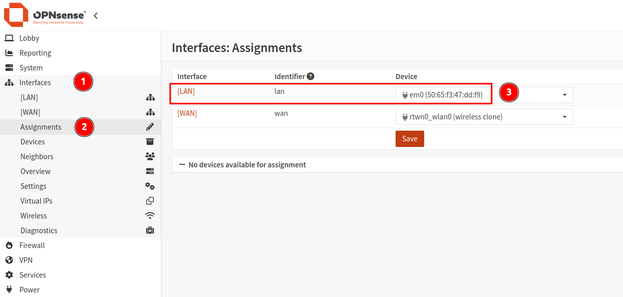
Create VLAN Interfaces
From within OPNsense, navigate to Interfaces > Assignments. Take note of the device connected to the LAN interface. This same interface will be used as the parent for the VLAN assignments.
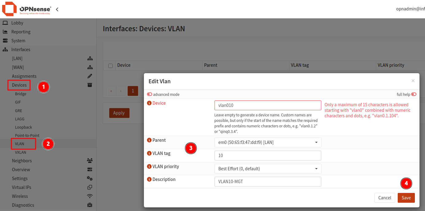
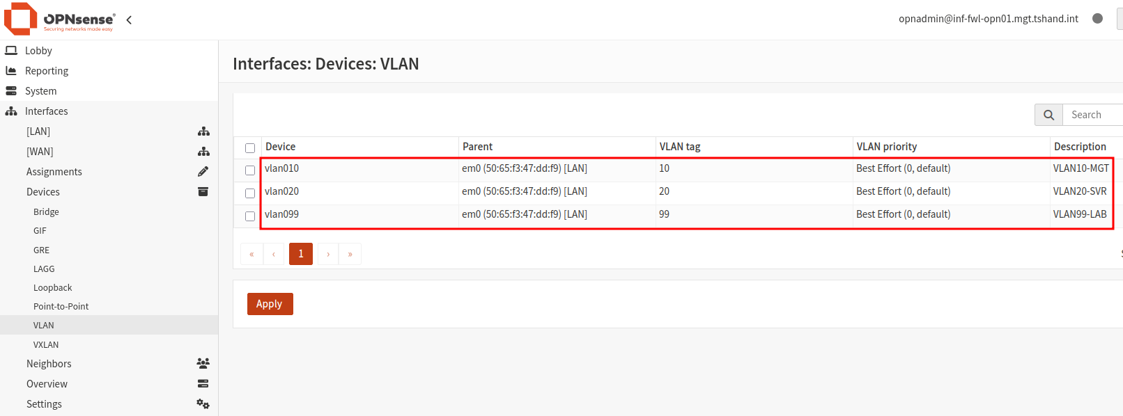
- From within the
Interfacesmenu section, navigate toDevices > VLAN. - Click the
+icon to create a new VLAN. - Enter the VLAN name (starting with “vlan0”), providing a tag ID number and description.
- Ensure to select the LAN device as the parent of this interface.
- Click save to create the VLAN interface.
- Repeat this process for all required VLANs.
When all VLANs have been added, click Apply.
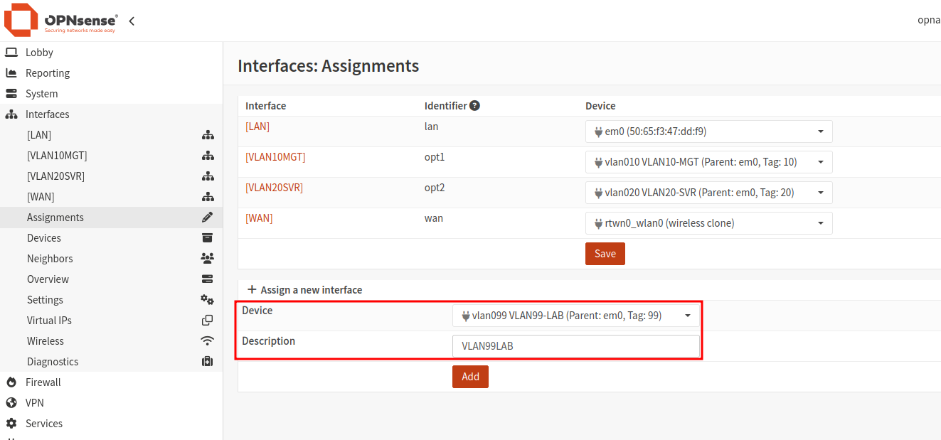
Assign VLAN Interfaces
- Navigate to
Interfaces > Assignments. - Under the section
Assign a new interface, select the first VLAN interface. - Provide a description in the text box provided - this will be used as the display name for the interface.
- Repeat this process until all VLANs have been assigned.
Configure VLAN Interfaces
This step is required to be performed for each VLAN interface created.
- Navigate to
Interfaces > [SELECT VLAN]. - Enable the interface using the check box provided.
- Set the
IPv4 Configuration TypetoStatic IPv4. - Enter an IP address to be used by the VLAN gateway, including the subnet mask (/24 in this case).
- Unless required, leave all other options as defaults.
- Click
Save, followed byApply Changes.
Setup DHCP (Optional)
- Note: If the automatic providing of IP addresses (DHCP) is not required, skip this step.
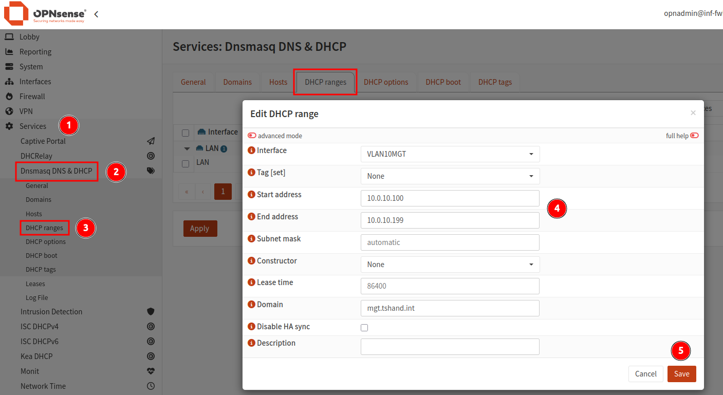
- Navigate to
Services > Dnsmasq DNS & DHCP. - Select the menu item
DHCP Ranges. - Click the
+icon to create a new DHCP range. - Select the VLAN interface, providing both a starting and ending IP address with optional domain name.
- All other setting can be left as defaults.
- Click
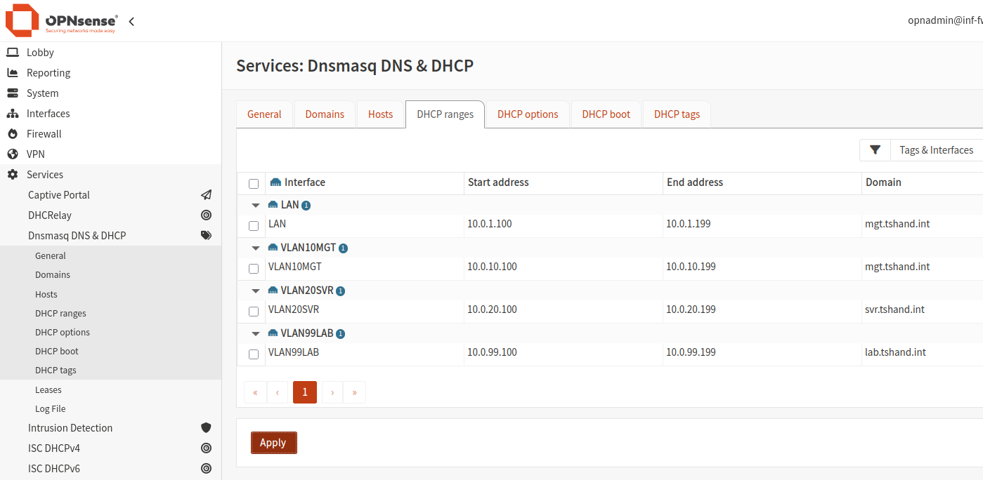
Save. Repeat for each of the remaining VLANs. - Once all VLAN DHCP ranges have been added, click
Apply.
Configure the DHCP server to “listen” on all required VLAN interfaces. Without this enabled, no DHCP addresses will be provided.
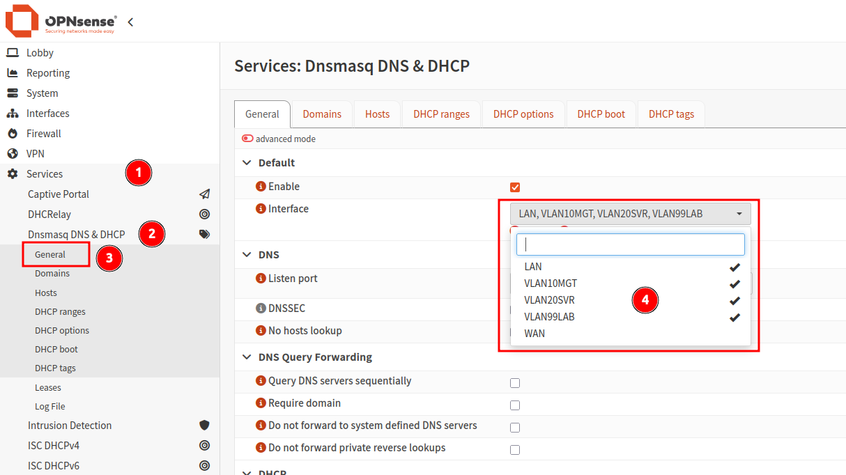
- Navigate to
Services > Dnsmasq DNS & DHCP > General. - Under the
Interfacedropdown, select all VLANs that require DHCP. - Scroll to the bottom of the page, and click
Apply.
Configuration: Switch VLANs
My TP Link TL-SG108PE switch provides support for 802.1Q VLAN tagging, along with port based VLAN configuration via the web UI.
- Note: Some switch manufacturers use different naming and terminology to refer to similar concepts. Consult your user guide if clarification is required.
Although Proxmox can be configured to use specific VLAN tags for the host communication (default bridge vmbr0 can be set to “vlan-aware”), I chose to use a port-based VLAN tagging approach (via PVID setting) as the switch ports will always be dedicated to the Proxmox hosts.
As the Proxmox nodes connected to ports 2 and 3 (with QDevice on port 4) are not tagging their traffic, they will use the tag value set in the PVID configuration.
Using the PVID setting allows for setting the VLAN ID on that port for untagged traffic. This means that when a device not configured to use a specific VLAN ID is connected to that port, it will be assigned to the VLAN configured under this setting.
- Note: The PVID defines the default VLAN ID assigned to any untagged incoming traffic on that switch port.
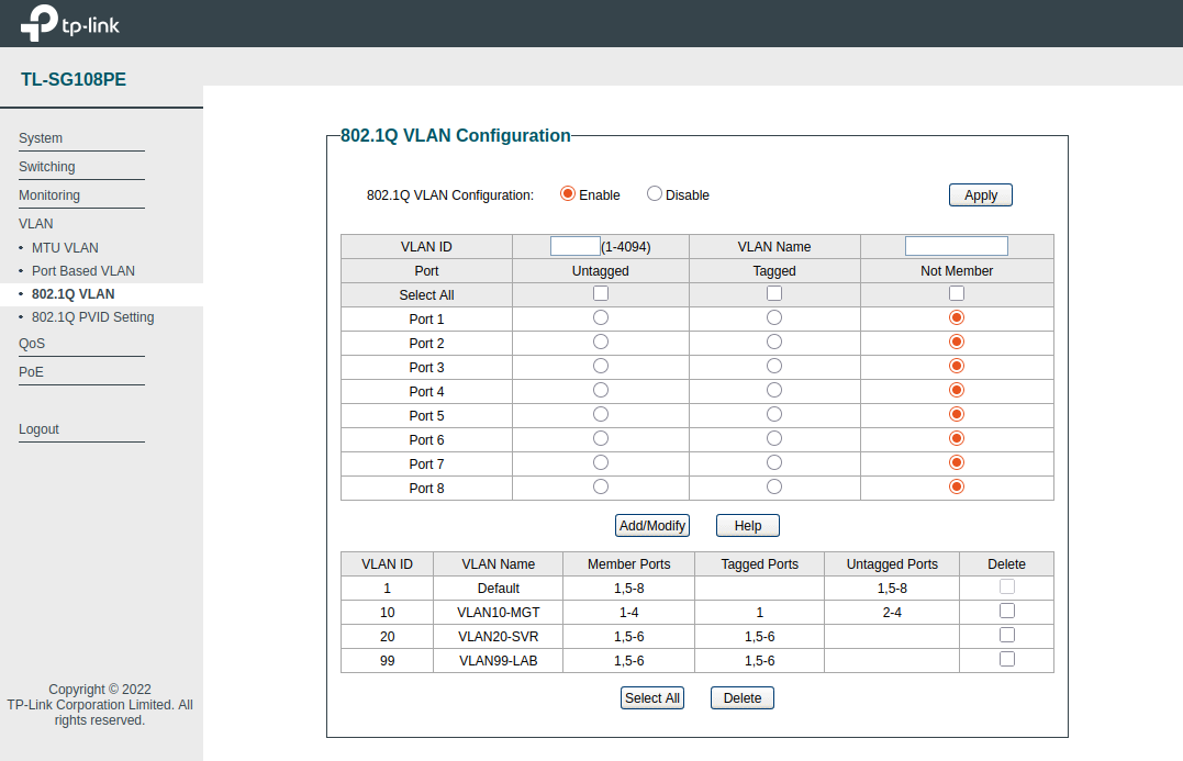
Switch - 802.1Q VLAN:
| VLAN | VLAN Name | Member Ports | Tagged Ports | Untagged Ports |
|---|---|---|---|---|
| 1 | Default | 1,5-8 | 1,5-8 | |
| 10 | VLAN10-MGT | 1-4 | 1 | 2-4 |
| 20 | VLAN20-SVR | 1,5-6 | 1,5-6 | |
| 99 | VLAN99-LAB | 1,5-6 | 1,5-6 |
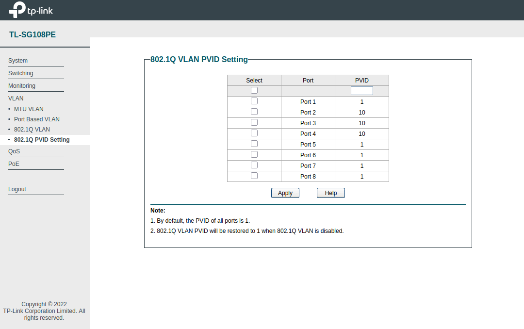
Switch - 802.1Q PVID (Port VLAN ID) Setting:
| Port | PVID |
|---|---|
| 1 | 1 |
| 2 | 10 |
| 3 | 10 |
| 4 | 10 |
| 5 | 1 |
| 6 | 1 |
| 7 | 1 |
| 8 | 1 |
Configuration: OPNsense Firewall Rules
By default, newly created interfaces do not have any rules allowing inbound traffic. Rules must be created to enable traffic flow between VLANs and gateway addresses.
- Note: When DHCP server is enabled on the VLAN interfaces, default rules are automatically added to allow for communication - no additional rules should be needed to enable traffic for DHCP services.
- Within OPNsense, navigate to
Firewall > Rules > VLAN10MGT. - By default, no custom rules should be present. Click the
+icon to create a new rule. - Add the required configuration as per below, repeat for remaining VLANs.
Allow internal communication:
|
|
Block VLAN99 (Lab) to VLAN10 (Management):
|
|
Testing Connectivity
A Note on Layer-2 Communication
As I was messing about with testing firewall block rules, I noticed that the Proxmox nodes were not affected. After a bit of research, I found that devices within the same VLAN, are in the same broadcast domain and the same Layer 2 segment. The switch handles the communication by forwarding frames based on their destination MAC addresses, without needing to involve a Layer 3 device (router or firewall, aka OPNsense).
Therefore, inbound traffic from Proxmox Node 1 (10.0.10.10) to Node 2 (10.0.10.11) will bypass the OPNsense firewall. Since both IP addresses reside on the same VLAN, the switch forwards the frames directly from port 2 to port 3. OPNsense only enforces firewall rules on traffic that passes through its interfaces.
Ping Test
Now with all the required configuration in place, running some test pings to the other VLAN interfaces from a Proxmox node shows successful results.
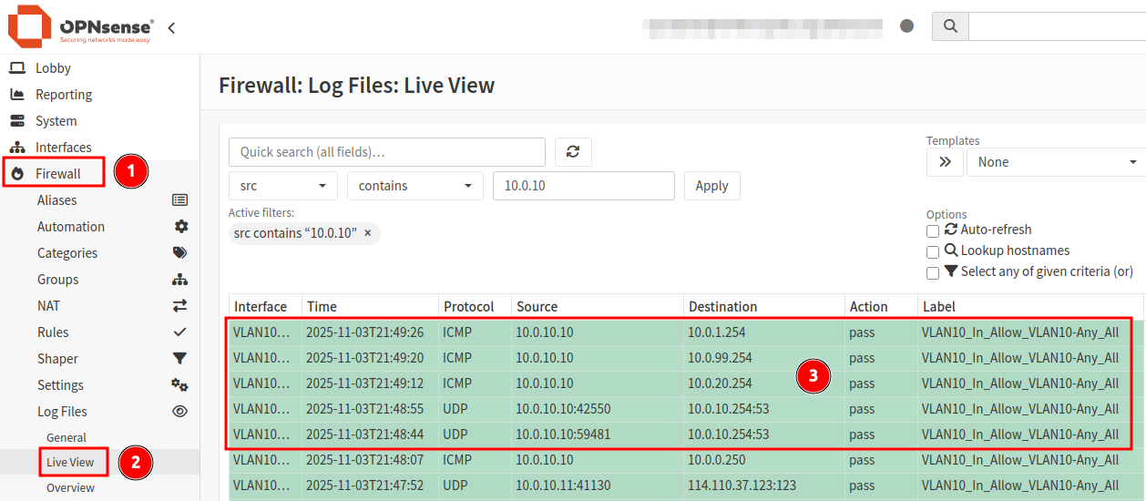
While open rules make testing and log reviews much easier, narrowing down firewall rules to only the minimum requirements will improve security posture and reduce risk.
Cover photo by Jordan Harrison on Unsplash